How to Read Engineering Drawings: A Beginner’s Guide to Orthographic Views
Learn how to read engineering drawings using orthographic views, front view, top view, side view, dimensions, symbols and section views.
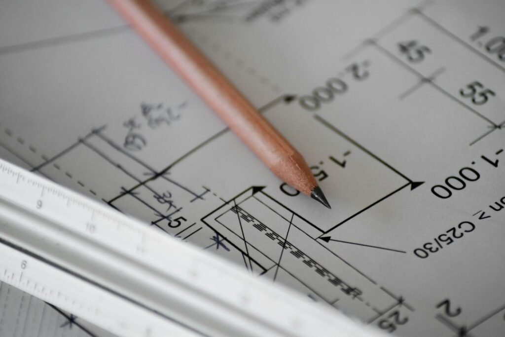
Learn how to read engineering drawings using orthographic views, front view, top view, side view, dimensions, symbols and section views.
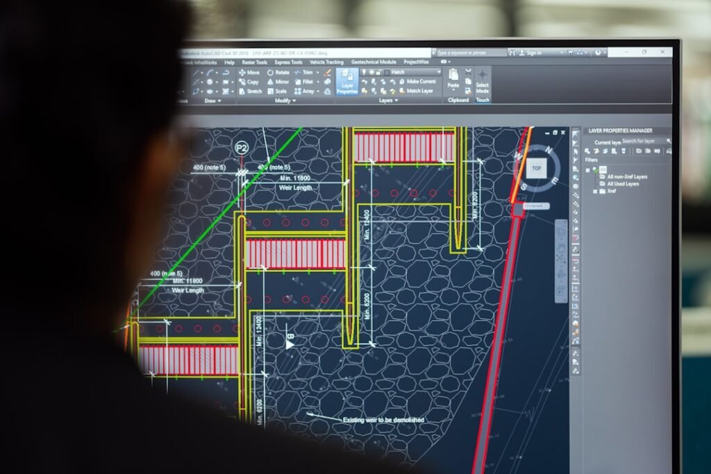
GD&T connects CAD intent with manufacturing and inspection requirements. A 3D CAD model can define shape, but manufacturing and inspection still need clear information about how features relate to each other. 2026 practical design update: make GD&T inspection-ready A useful drawing should let an inspector establish the datum reference frame and understand what is being
Mesh convergence helps determine whether an FEA result is stable enough for the engineering decision. Finite Element Analysis can make a mechanical design review much more powerful, but only when the simulation is set up and interpreted correctly. 2026 practical design update: document the convergence decision For important studies, save a small convergence table with

Plastic part geometry should be reviewed together with the mold and production process. Injection molding can produce thousands or millions of plastic parts, but the economics work only when the component is designed for the molding process. 2026 practical design update: review the mold before freezing the CAD Before tool release, review the part with
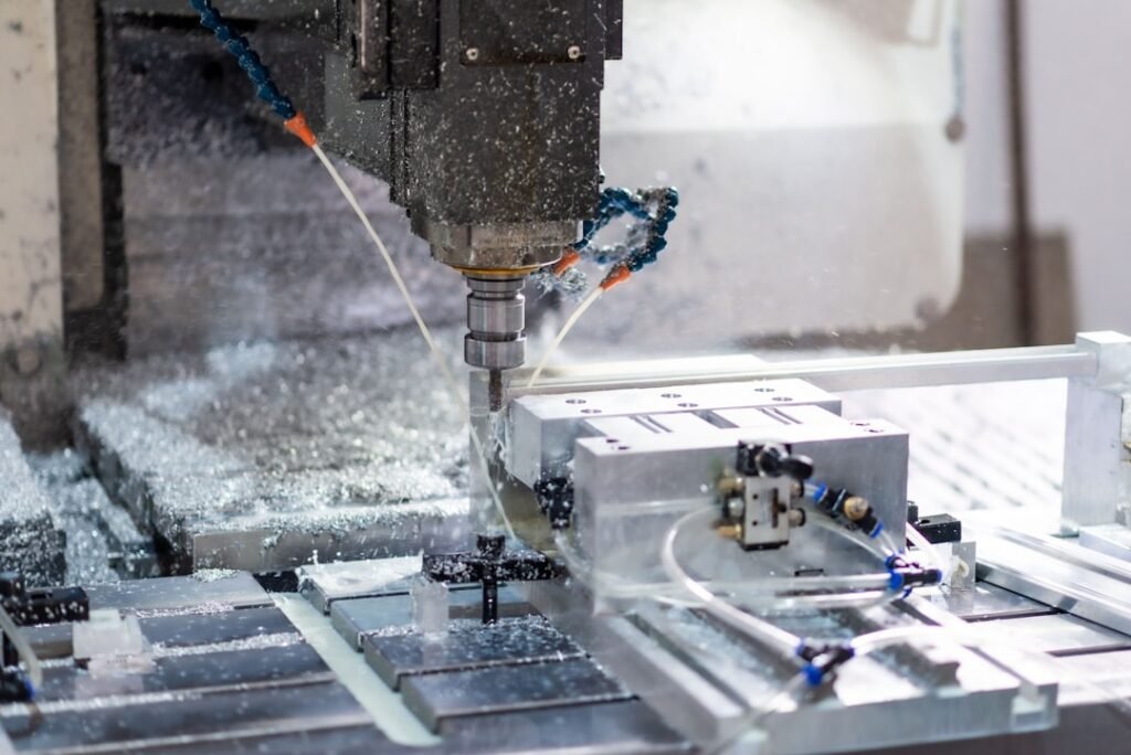
Good CNC DFM connects CAD geometry with tooling, workholding and inspection. A CAD model can be geometrically correct and still be expensive or difficult to machine. 2026 practical design update: design for the whole production route For a production-ready part, review the complete route rather than only the milling geometry. Ask how the raw stock
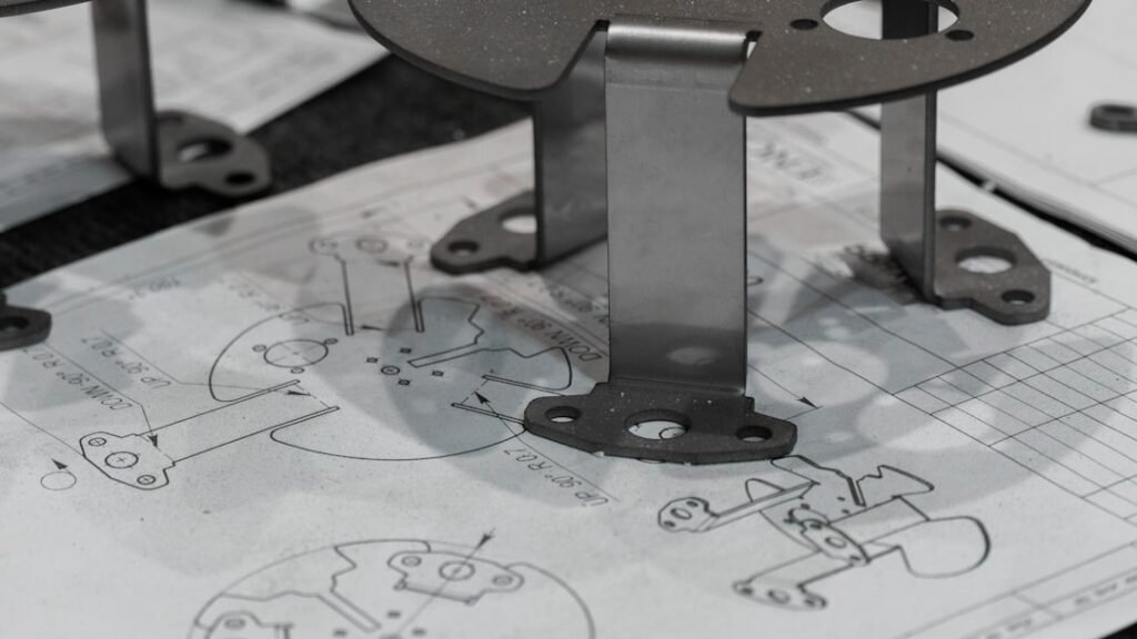
Sheet-metal CAD design must connect the 3D model to real fabrication. Designing a sheet metal component in CAD is not simply a matter of drawing a plate, adding bends, and exporting a flat pattern. 2026 practical design update: validate the manufacturing loop Before release, treat the workflow as a loop: CAD model → flat pattern
Introduction Design engineering serves as the cornerstone of mechanical innovation, revolutionising industries and transforming ideas into tangible realities. It is a dynamic and multidisciplinary field that merges the principles of engineering, creativity, and problem-solving. In this blog post, we will delve into the world of design engineering, exploring its significance, key principles, methodologies, and the
Introduction: Mechanical engineering relies heavily on Computer-Aided Design (CAD) software to design and analyse complex mechanical systems. CAD software has revolutionised the field, enabling engineers to create intricate designs with precision and efficiency. In this blog, we will explore the different types of CAD software available for mechanical engineering professionals. From industry-leading software to specialised

The CAD software industry is constantly evolving, and there are several popular software options that are widely used in the mechanical engineering field. Here are some of the CAD software currently used in the industry for designing: It offers a comprehensive set of tools for 3D modelling, simulation, and visualisation. SolidWorks provides features like part
The Best Free 3D CAD Software for Mechanical Engineering Projects Introduction: In the ever-evolving world of mechanical engineering, the ability to create precise and detailed 3D models is essential. Computer-Aided Design (CAD) software plays a crucial role in this process, enabling engineers to design, analyse, and simulate mechanical components and systems. However, acquiring a powerful CAD