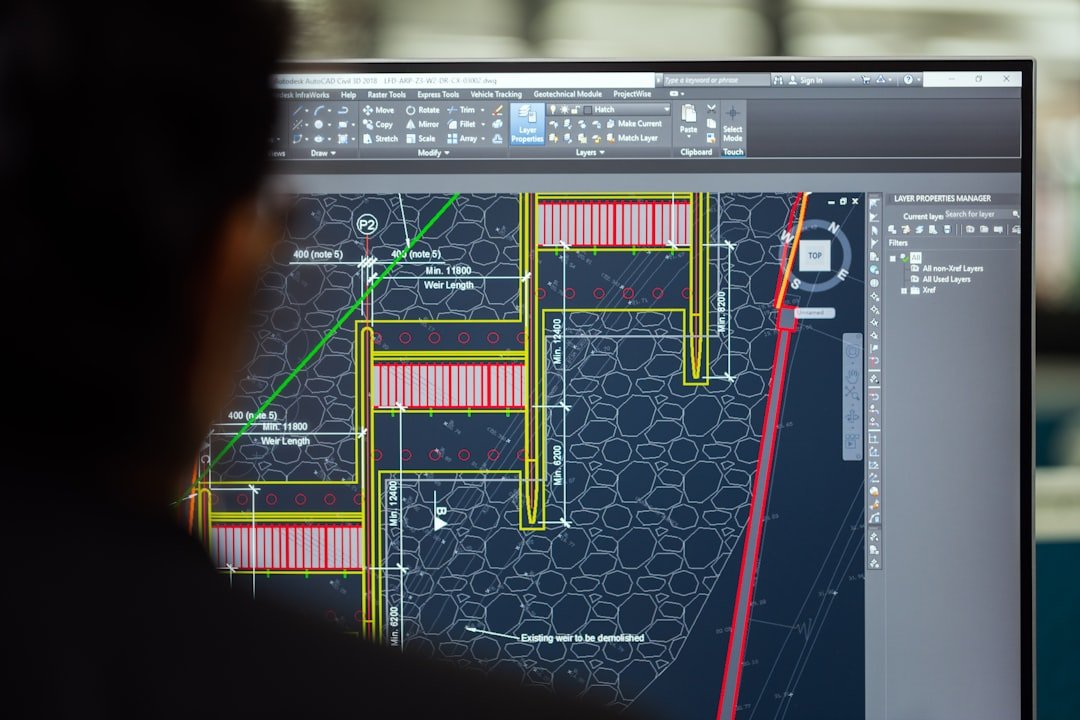
A 3D CAD model can define shape, but manufacturing and inspection still need clear information about how features relate to each other.
2026 practical design update: make GD&T inspection-ready
A useful drawing should let an inspector establish the datum reference frame and understand what is being controlled without guessing the designer’s intent. During review, ask three questions: what function is being protected, which feature establishes location, and how will the requirement actually be measured? For critical features, coordinate the drawing with the inspection method and manufacturing capability. Avoid adding a tight geometric tolerance unless the assembly or performance requirement justifies it.
That is where GD&T, or Geometric Dimensioning and Tolerancing, becomes valuable. GD&T gives engineers a systematic language for describing allowable variation in form, orientation, location and relationships between features.
Why GD&T matters in mechanical design
Traditional plus-and-minus dimensions can describe size, but size alone does not always control function. Imagine a plate with four mounting holes. Each hole might have the correct diameter, yet the pattern could still be shifted or rotated enough to prevent assembly.
GD&T allows the drawing to communicate functional relationships. Instead of controlling every possible error with separate dimensions, the designer can establish datums and define how features are allowed to vary relative to them.
Start with functional datums
A datum is a theoretically exact reference used to establish a coordinate system for manufacturing and inspection. Datum selection should follow function. Ask which surface or feature actually locates the component in the assembly.
A common mistake is selecting datums because they are convenient on the CAD model rather than because they represent how the part functions. The datum structure should make sense to the machinist, inspector and assembly engineer.
Understanding position tolerance
The position control is one of the most widely used GD&T tools. It controls the location of a feature relative to specified datums. For a hole pattern, position tolerance can be more useful than independently dimensioning every center location with very tight linear tolerances.
Profile controls complex shapes
Profile of a surface can control the location and form of a surface relative to the true profile. It is especially useful for curved, blended or freeform geometry where ordinary linear dimensions become difficult to apply.
Form controls shape without a datum
Form controls such as straightness, flatness, circularity and cylindricity describe the shape of a feature. These controls generally do not require a datum because they address the feature’s own form.
Flatness, for example, controls how much a surface may deviate from an ideal plane. It does not by itself establish where that surface is located in the assembly. That distinction matters when choosing between a form control and an orientation or location control.
Orientation controls need a reference
Parallelism, perpendicularity and angularity control the orientation of a feature relative to a datum reference. If a mounting surface must be perpendicular to a primary locating face, perpendicularity can communicate that requirement directly.
Do not over-tolerance the drawing
More tolerances do not automatically mean a better drawing. Every tight tolerance can increase manufacturing and inspection cost. The objective is to control variation where it affects function.
Start with the assembly requirement. Identify what must fit, rotate, seal, locate or carry load. Then assign tolerances that protect that function. Non-critical features can often use a suitable general tolerance.
GD&T and CAD models should agree
The 3D model, drawing and manufacturing data should tell the same story. A hole pattern controlled tightly in the drawing should not be accidentally changed in CAD without updating the drawing. Revision control is therefore part of good GD&T practice.
Practical GD&T review checklist
- Are the datums selected from functional requirements?
- Does each critical feature have an appropriate control?
- Are hole patterns controlled for location rather than only size?
- Are form and orientation requirements clearly separated?
- Are tolerances realistic for the manufacturing process?
- Can the inspection team establish the datum reference frame?
- Does the CAD model match the drawing revision?
- Have unnecessary tight tolerances been removed?
Learning GD&T as a CAD engineer
CAD engineers become more effective when they understand how a part will be manufactured and inspected. Practice by taking a simple bracket and identifying its primary, secondary and tertiary locating features. Then decide which dimensions control size and which geometric controls protect assembly.
Do not memorize symbols in isolation. Learn what functional problem each control solves. That approach makes GD&T easier to apply during real design reviews.
Final thoughts
GD&T for mechanical design is ultimately about communicating function. Datums establish the reference system, geometric controls define allowable variation, and dimensional tolerances describe size. When those elements are chosen logically, the drawing becomes easier to manufacture, inspect and assemble.
SEO keywords: GD&T for CAD engineers, geometric dimensioning and tolerancing, datum reference frame, position tolerance, profile tolerance, mechanical drawing, engineering drawing standards, GD&T basics.