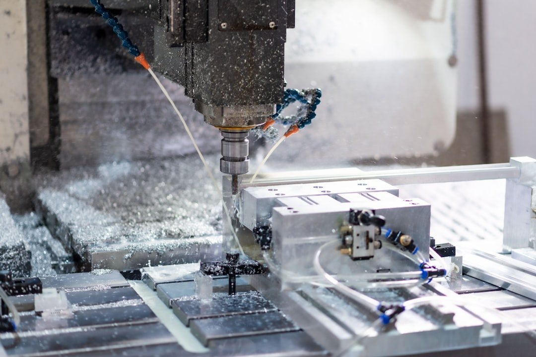
A CAD model can be geometrically correct and still be expensive or difficult to machine.
2026 practical design update: design for the whole production route
For a production-ready part, review the complete route rather than only the milling geometry. Ask how the raw stock will be purchased, how the first setup will establish datums, where probing or inspection will occur, how tools will reach each feature, and whether secondary operations are required. When quoting matters, also flag features likely to increase cycle time—deep pockets, very small tools, excessive surface finishing, multiple setups and unusually tight tolerances. A design that removes one avoidable setup can be more valuable than a small geometry optimization.
CNC machining is a manufacturing process, not simply a way of converting a STEP file into metal. Tool access, cutter diameter, workholding, material, tolerance, surface finish and inspection requirements all influence the final part. A practical CNC machining DFM review catches these issues before the design reaches the machine shop.
What design for CNC machining means
Design for manufacturability means making engineering decisions that allow a part to be produced consistently with the intended process. For CNC milling and turning, this means considering how tools approach geometry, how the workpiece is held, how many setups are required, and which dimensions genuinely need tight control.
Think about tool access
The cutting tool needs a clear path to the feature. Deep pockets, narrow slots and tall internal walls can force a shop to use long tools. Long tools are less rigid and can deflect or chatter. If a feature can be widened, shortened or redesigned without affecting function, the change can improve machining stability.
Design internal corners realistically
A common DFM mistake is placing a zero-radius internal corner in a milled pocket. A round cutter cannot create that geometry in one normal milling operation. A larger internal radius usually improves tool life and allows a larger, more rigid cutter.
When a sharp corner is functionally required, consider a corner relief, dog-bone feature, wire EDM, broaching, or another suitable process. The right choice depends on function and production quantity.
Avoid unnecessary tight tolerances
Tolerance is one of the biggest cost drivers in precision machining. A general dimension may be easy to produce, while a very tight tolerance can require additional operations, specialized tooling and inspection.
Do not apply tight tolerances simply because CAD displays many decimal places. Assign tighter tolerances to dimensions that control assembly, sealing, motion, alignment or performance. Let non-critical dimensions use an appropriate general tolerance.
Select surface finishes with purpose
Surface finish should communicate a functional requirement. A bearing surface, sealing face or visible cosmetic surface may need special treatment, while an internal non-functional face may not. Requiring a very fine finish everywhere can add unnecessary machining time.
Design for workholding
The machine shop must hold the part securely. Thin walls, tiny tabs and awkward shapes can make fixturing difficult. Before releasing a complex part, ask how the blank will be held and whether the design provides enough material for clamping.
For multi-sided parts, consider how many setups are needed. Every additional setup introduces another opportunity for alignment error and increases handling time. A small geometry change can sometimes allow most machining to happen in one setup.
Choose material carefully
Material selection affects cutting behavior, tool life, burr formation, heat generation and dimensional stability. Aluminium, mild steel, stainless steel, brass, engineering plastics and hardened alloys all behave differently during machining.
Consider hole manufacturing
Holes are common CNC features, but their design still matters. Standard drill sizes can reduce tooling requirements. Very deep small-diameter holes can be difficult because chips have limited space to escape and the tool becomes vulnerable to deflection.
Reduce unnecessary machining volume
Large pockets remove material and consume machine time. If a component can use ribs, webs, pockets or a different starting stock size without sacrificing stiffness, material usage and machining time can be reduced.
Make drawings communicate manufacturing intent
A good CNC machining drawing should show material, critical dimensions, tolerances, datums, surface finish, threads, edge-break requirements and special inspection requirements. The 3D CAD model and drawing should agree.
Practical CNC DFM checklist
- Can every feature be reached by a practical cutting tool?
- Are internal corners compatible with cutter geometry?
- Are tolerances limited to functional requirements?
- Can the part be held securely?
- Can the number of setups be reduced?
- Are hole sizes practical for standard tooling?
- Is the material grade correct?
- Are surface finishes justified?
- Are deep pockets and thin walls necessary?
- Does the drawing clearly communicate inspection requirements?
Final thoughts
The best CNC-machined designs are not merely accurate models. They are models that understand the machine shop. A designer who thinks about cutters, fixtures, tolerances, material and inspection while creating the CAD model can prevent expensive changes later. Use DFM as part of the design process rather than as a final approval step.
SEO keywords: CNC machining DFM, CNC design guidelines, CNC machining cost reduction, mechanical design for manufacturing, CNC milling design, machining tolerances, CNC part design.