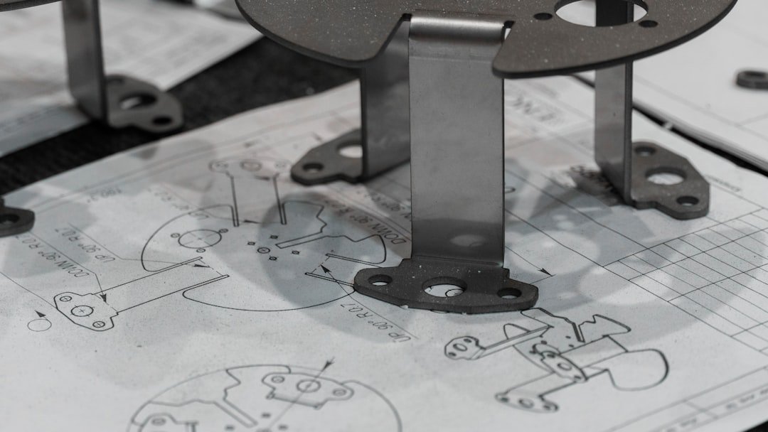
Designing a sheet metal component in CAD is not simply a matter of drawing a plate, adding bends, and exporting a flat pattern.
2026 practical design update: validate the manufacturing loop
Before release, treat the workflow as a loop: CAD model → flat pattern → cutting → forming → inspection → feedback. Record actual bend results from production and use that information to improve the approved bend table or sheet-metal library. Also check the DXF layer convention, grain direction, bend notes and revision before sending files to a supplier. This small feedback loop can prevent repeated trial-and-error on future parts.
A manufacturable model has to account for material thickness, bend radius, tooling, springback, bend sequence, and the way the fabricator will actually form the part. A strong SolidWorks sheet metal design workflow starts with manufacturing intent rather than geometry alone.
Why sheet metal needs a different CAD workflow
Sheet metal begins as a flat blank and becomes a three-dimensional component through bending or forming. The neutral axis does not always sit exactly at the middle of the thickness, so the developed length of a finished part is not simply the sum of outside dimensions. If the flat pattern is wrong, a laser-cut blank can be too long or too short even when the finished 3D model looks perfect.
SolidWorks stores sheet metal information inside the model. A designer can define material thickness, bend radius, bend allowance or bend deduction, and then generate a flat pattern. These settings should reflect the actual fabrication process. A generic value copied from another project may not work for a different material, thickness, press brake, tooling setup, or supplier.
Understanding K-factor
The K-factor describes the location of the neutral axis through the sheet thickness during bending. It is expressed as a fraction of material thickness. A simplified relationship is: neutral-axis distance from the inside surface = K-factor × thickness. The value is not a universal material constant. It changes with material behavior, thickness, bend radius, tooling and forming conditions.
For production work, use a supplier-approved K-factor or bend table whenever available. After manufacturing feedback is collected, the value can be refined. This is more reliable than manually changing dimensions every time a flat pattern does not match the shop result.
Bend allowance and bend deduction
Bend allowance is the length of material consumed by the bend along the neutral axis. For a simple bend, it can be approximated from the bend angle, inside radius, material thickness and K-factor. The equation is useful for understanding the relationship, but production calculations should follow validated shop data.
Bend deduction is another method used to calculate flat length from the outside dimensions of a bent component. Both methods can work. The important point is to understand which method your CAD system, drawing and fabrication process are using.
Choosing the inside bend radius
Bend radius should be selected with the material and forming process in mind. A radius that is too small can cause cracking, excessive thinning, marking, or inconsistent forming. A very large radius can create packaging or tooling problems. Aluminium, mild steel, stainless steel and high-strength materials can require different practical minimum radii.
Designing bend reliefs
Bend relief prevents material from tearing or deforming near the end of a bend. Without suitable relief, the bend can continue into an adjacent edge and create an unwanted bulge. Rectangular and tear-shaped reliefs are common, but the fabricator’s standard should take priority.
Keep holes and features away from bends
Holes, slots and cut-outs placed too close to a bend can distort during forming. The required clearance depends on thickness, radius, tooling and feature size. A good CAD review therefore checks the distance from every critical cut feature to the bend zone before releasing the drawing.
Using the SolidWorks flat pattern correctly
After the 3D model is complete, generate the SolidWorks flat pattern and verify the overall blank size, bend lines, bend directions, grain direction where relevant, and all reliefs. If the model is going to a laser or CNC punch process, confirm that the exported DXF contains the intended geometry and does not include construction entities.
Sheet metal DFM checklist
- Confirm material grade and thickness.
- Use a validated bend table, bend allowance or K-factor.
- Check the practical inside bend radius.
- Provide suitable bend reliefs.
- Keep holes and slots away from high-deformation zones.
- Check grain direction where it matters.
- Confirm the flat pattern with the fabrication process.
- Dimension critical formed features clearly.
- Identify coating, deburring and surface-finish requirements.
- Review difficult parts with the fabricator before release.
Common mistakes to avoid
One common mistake is designing a sheet metal component as a generic solid and thinking about manufacturability only at the drawing stage. Another is using the same K-factor for every material and thickness. A third is ignoring bend sequence. A component may be theoretically formable but impossible to position correctly in a press brake because a previous flange blocks the tooling.
Another frequent problem is confusing nominal CAD geometry with manufacturing capability. The CAD model represents design intent; it does not automatically guarantee that every fabrication method can reproduce it.
Final thoughts
A strong sheet metal design workflow connects CAD geometry to real fabrication. SolidWorks makes the process efficient, but the quality of the result depends on the engineering decisions behind the model. Use supplier data, validated bend tables and practical DFM checks. When the flat pattern, drawing and manufacturing process agree, the design becomes easier to quote, fabricate, inspect and revise.
SEO keywords: SolidWorks sheet metal design, bend allowance, K-factor, sheet metal flat pattern, sheet metal DFM, press brake design, sheet metal fabrication.